|
|
|
|
|
|
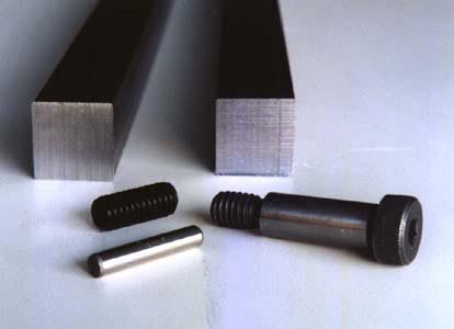
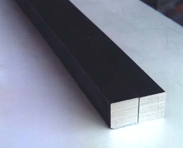
| The four different types of items that push/pull style planing forms are composed of: 3/4" cold-rolled key-stock, dowel pins, set screws, and shoulder bolts. The length of the two bars and the quantity of bolts, etc. you will need depends on what length you decide to make your forms. Most split-cane bamboo fly rod makers use forms that are five to six feet in length. The key-stock is sold in twelve foot lengths, so a single piece can be cut in half to create two six foot long sections. You can see what tools and other items are required by viewing the materials list. |
|
|
|
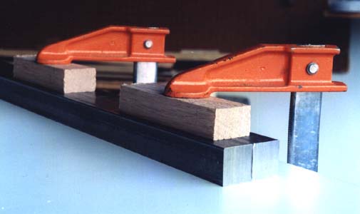
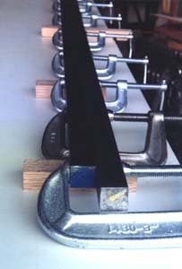
| The first step in building your fly rod planing forms will be to place the two bars onto a flat surface and clamp them down (in this case, a piece of factory finished particle board shelving is being utilized as the work surface). Wooden blocks are being used to protect the surfaces of the bars from being marred by the f-clamps. | |
|
|
|
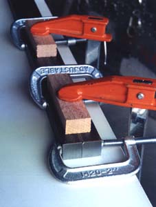
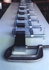
| Once the bars have been firmly clamped to the smooth work surface, begin to place c-clamps down the length of the bars. If you are making forms that are 6' in length, you may need ten to twelve 2" c-clamps to do this. Also, if you only have a couple of f-clamps, simply remove them from an area after the c-clamps have secured it, and reuse them. | |
|
|
|
| After all of the c-clamps have been applied to the bars, remove the f-clamps that were being used to hold the bars down on the work surface. The reason why the bars were initially clamped down to the tabletop was to ensure that the surface of each bar that faced the tabletop would be made as flush with one another as possible. | |
|
|
|
| The next step is to flip the bars over, exposing the surfaces that had previously been clamped down onto the tabletop in order to make them flush. You will need to support the bars on wooden blocks so that the c-clamps will clear your work surface and allow the bars to rest level on the table. Once this is accomplished you will be ready to begin draw-filing the two bars in order to make these surfaces even more truly flat and flush with one another (you will probably need to clamp the bars into position on the table so they do not slide while you are filing). | |
|
|
|
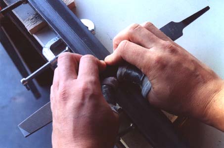
| This image shows the proper way to hold a 10" mill bastard file while draw-filing the surfaces of the bars. You will need a protective wrapping on your thumbs to avoid serious blisters from where the skin contacts the edge of the file (an even better idea, that was shared with me by Donald Yelton, would be to epoxy the file to a strip of hardwood. This would make it more comfortable to hold, and enable you to apply more force to the file). Keeping your hands near the center of the file may help you to keep it from canting to one side or the other. In this image you can see the light areas on the surface of the bars where the file is making contact. The darker areas are places where the file is not yet removing material from the bars. | |
|
|
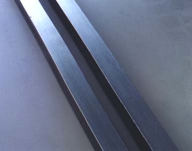
| Once filing has created a uniform sheen on the surface of the bars, the c-clamps are removed and the metal shavings are cleaned from each bar. These two surfaces that have just been filed will be placed face to face, as shown in the next image. |
|
|
|
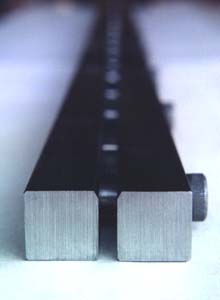
| In this image the two bars are oriented so that the surfaces that were just filed are in contact with one another. The smooth finish obtained by filing allows the two bars to rest surface to surface without there being any gaps in the joint between them. The next step will be to drill the holes for the dowel pins and shoulder bolts. | |
|
|
|
|
|
|
|
|
This fly fishing site created and maintained by Thomas Penrose
| For more detailed information on split cane fly rod making, look at these books: |
| A Master's Guide to Building A Bamboo Fly Rod, by Everett Garrison with Hoagy B. Carmichael. |
| Handcrafting Bamboo Fly Rods, by Wayne Cattanach. |
| How to Make Bamboo Fly Rods, by George W. Barnes. |
Fundamentals
of Building a Bamboo Fly-Rod, by George E. Maurer and Bernard P. Elser |
| Constructing Cane Rods: Secrets of the Bamboo Fly Rod, by Ray Gould |
| Splitting Cane: Conversations With Bamboo Rodmakers, by Ed Engle |
| The Lovely Reed: An Enthusiast's Guide to Building Bamboo Fly Rods, by Jack Howell |
| Cane Rods: Tips & Tapers, by Ray Gould |
All images and text copyrighted ©1997, 2008
| The informational content of this bamboo fly rod and fly fishing site is not warrantied in any way or form, and any use of said content are at the reader's own risk, the author shall not be held responsible in any way for any damages or injuries arising from the content of this web site. Common safety practices are encouraged at all times, and the proper and safe use of all power tools and safety equipment (eye goggles, etc.) is the responsibility of the user. |