Thomas Penrose's Bamboo Fly Rod Pages

Handcrafting Your Own Set of Planing Forms (Page 3)

Page 1 Page 2 Page 3 Page 4

Home

ftapping.JPG (10290 bytes)

 
You are now ready to begin tapping the threads for your shoulder bolts and set screws. Be sure to use a good lubricant when doing this (I use engine cam pre-lube), and to back out the tap bit to remove the metal filings each time it begins to resist turning. Tapping bits are very brittle, and will break easily if forced (be sure to use only high quality tap bits). You will generally only be able to turn the 5/6"-18 tapping bit about 1/8th of a revolution before it jams and has to be backed up a half revolution or so in order to clear the metal chips that are causing it to stop cutting. It takes about three hours to tap all of the threads for the shoulder bolts and set screws. If you should break off a bit, try to find a machine shop that is willing to help remove it. Alternately, you can purchase the tool that is used to do this, but it may not be an item that is easy to find. It is best to proceed slowly, and avoid breaking off any tap bits in your planing forms.

fhalves.JPG (6945 bytes)

 
This image shows the two form halves with the thread tapping completed and the dowel pins and set screws in position. The next step will be to join the halves with the shoulder bolts (be sure to clean the threaded holes of any metal chips left over from the tapping procedure before putting in the shoulder bolts or set screws).

fbolted.JPG (8636 bytes)

The two form halves bolted together. The surfaces of each side will now need to be draw-filed in order to make them as flush with one another as possible. Once this task is completed the 60° tapered groove can be filed down the center of each side of the forms in order to complete the project.

ffiling2.JPG (7333 bytes)

 
The amount of time it will take to draw-file your forms will depend in part on how square your bars were to begin with, as well as how good a job you did at clamping them together prior to and during the drilling process. The object here is to file until there is a uniform sheen on the surface of the bars.

ftool.JPG (11058 bytes)

Once the draw-filing is completed you will be ready to begin filing the 60° tapered grooves down the middle of each side of the forms. To do this you will make a special tool by epoxying a 2"-3" broken off section of a triangular file to a block of high grade plywood. It is best to use a section of file that is closer to the handle end, since the tip end of the file will have a more pronounced taper. The file section may need to be recessed into a dado (as it has in the tool in this image) so that it does not protrude out so far that it will strike the shoulder bolts as it is pushed back and forth in the forms. If you need to cut a dado be sure to use a table saw, radial arm saw, router, or other precision tool, since it is imperative that the file is not glued into a dado that cants it to one side or the other (this would cause the groove you are filing to assume an imperfect "V" shape). Remember, you are after a precise equilateral triangular groove here. Alternately, you can epoxy a strip of plexiglass on either side of the file in order to lessen its cutting depth if you do not have access to a router or table saw. It will probably be necessary to clamp the strips after gluing in order to squeeze out any excess epoxy that might otherwise cause the two plexiglass strips to not be glued perfectly flat against the plywood block.

ftoolhex.JPG (7507 bytes)

 
To file the 60° tapered groove in the forms you will be adjusting the bars so that they will be set wider apart at the tip end, and closer together at the butt end while you are filing. This way the file tool will take off more material at the butt end and progressively less material toward the tip end. The first step in this adjustment process is to loosen all of the shoulder bolts by turning them out about 1/4". Next, adjust the width of the butt end of the forms (using allen wrenches) so that the sole of the file tool is caused to rest just barely above the surface of the bars (so that the file will be removing metal in this spot when it is pushed back and forth between the form halves). Tighten the shoulder bolt and set screw at this single location to lock this adjustment in place.

fdial1.JPG (8090 bytes)

 
Next, take the measurement of the the distance between the forms at this location using your dial caliper (the dial on the caliper in this image is reading .165 inches). Make a note of the reading when you make this measurement (your reading will almost certainly be different than the .165 that I obtained).


fdial2.JPG (8657 bytes)

 
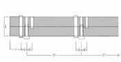
The next step of the process is to adjust the width of each successive station on the forms so that the groove we create with the filing tool has an approximately .005 inch decrease in its depth from one station to the next (i.e. this means that the slope of the taper of the groove decreases by approximately .001" per inch over the length of the forms [moving from the butt end to the tip end], since each station is 5 inches apart). This mathematical process is complicated by the manner in which the length of each side of our equilateral triangular groove differs from the depth of the groove 
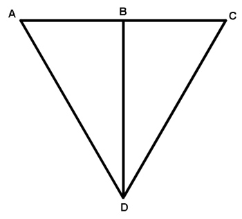
itself. If you look at the figure below, you will see that the length of each of the sides (lines AC, CD, and DA) of the equilateral triangle are greater than the triangle’s height (line BD). Since we want the depth of our groove to decrease by .005 inches from one station to the next, the width of the groove will actually end up needing to be greater than .005, and should actually be .00577" (since .005/sin60 = .00577. Another way of looking at it is that the side of an equilateral triangle is approx 15.5% greater than the triangle's height). Hence, if we set the width between the forms so that each station is .00577" more widely spaced than the previous station, the groove we cut would end up being .005" shallower from one station to the next, and this is what is correct. However, using this .00577 measurement poses its own problems, since we are now dealing with ten thousandth of an inch increments, which are not practical for our purposes. Likewise, rounding these numbers off might result in problems keeping the slope of the groove uniform, and uniformity is our main concern here. Whether the slope of the groove falls at .001" per inch or .0015" per inch is not really important, since the adjustability of the bolts at each station of the forms will allow you to set the forms to make virtually any rod taper you want to make.  What is important is that this slope is uniform and has no dips or flat spots in it.  Consequently, I will suggest that you simply use a .006 increment between stations, or .005, and not worry about using a .00577 width increment.   For the sake of these instructions I will simply stick with .005, since it is what I have used in the past.  However, a .006 width will actually give results that are closer to the .005 groove depth that is commonly prescribed.

formTRI.jpg (22401 bytes)

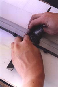
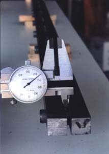
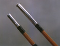
To figure out the width dimensions I will set at each station using my dial calipers, I take the .165 measurement I had come up with above, and add .005 to it, giving me .170 (which is what the caliper is set on in the photo above), which is the measurement I use to set the width at the next station following the one I had set at .165.  I then add .005 to this .170 measurement, giving me .175, which is the dimension for the third station.  I will then continue to add .005 to each sum in order to come up with the width to set between the forms at each successive shoulder bolt station, so that each station is set .005 further apart than the previous one. 

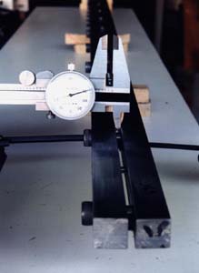
Once you finish setting the station width adjustments with your dial calipers it is essential to double check them again, since the settings at one station can change slightly as you loosen or tighten the bolt at the station adjacent to it.  Make sure each one is set to be .005" wider that the one you set before it.

NEXT PAGE>
Page 1 Page 2 Page 3 Page 4

Home

asmgreen.yellow.jpg (2156 bytes)

waldronsm.JPG (1875 bytes)

My Split Cane Fly Rod Building Pages

Tonkin Cane for Fly Rods

Making Planing Forms using Lawrence Waldron's Layout

smferrule2.JPG (4295 bytes)

smferrule3.JPG (5769 bytes)

corksm.jpg (11759 bytes)

Determining Ferrule Positioning on a 2 Piece Fly Rod

Determining Ferrule Positioning on a 3 Piece Fly Rod

Turning Cork Grips with a Hand Drill


This fly fishing site created and maintained by Thomas Penrose

For more detailed information on split cane fly rod making, look at these books:
A Master's Guide to Building A Bamboo Fly Rod, by Everett Garrison with Hoagy B. Carmichael.
Handcrafting Bamboo Fly Rods, by Wayne Cattanach.
How to Make Bamboo Fly Rods, by George W. Barnes.
Fundamentals of Building a Bamboo Fly-Rod, by George E. Maurer and Bernard P. Elser
Constructing Cane Rods: Secrets of the Bamboo Fly Rod, by Ray Gould
Splitting Cane: Conversations With Bamboo Rodmakers, by Ed Engle
The Lovely Reed: An Enthusiast's Guide to Building Bamboo Fly Rods, by Jack Howell
Cane Rods: Tips & Tapers, by Ray Gould

All images and text copyrighted ©1997, 2008

The informational content of this bamboo fly rod and fly fishing site is not warrantied in any way or form, and any use of said content are at the reader's own risk, the author shall not be held responsible in any way for any damages or injuries arising from the content of this web site. Common safety practices are encouraged at all times, and the proper and safe use of all power tools and safety equipment (eye goggles, etc.) is the responsibility of the user.